MIT Engineers Develop a Fully 3D-Printed Electrospray Engine
Ideal for propelling tiny satellites, the lightweight devices could be produced onboard a spacecraft and cost much less than traditional thrusters.
Adam Zewe | MIT News
An electrospray engine applies an electric field to a conductive liquid, generating a high-speed jet of tiny droplets that can propel a spacecraft. These miniature engines are ideal for small satellites called CubeSats that are often used in academic research.
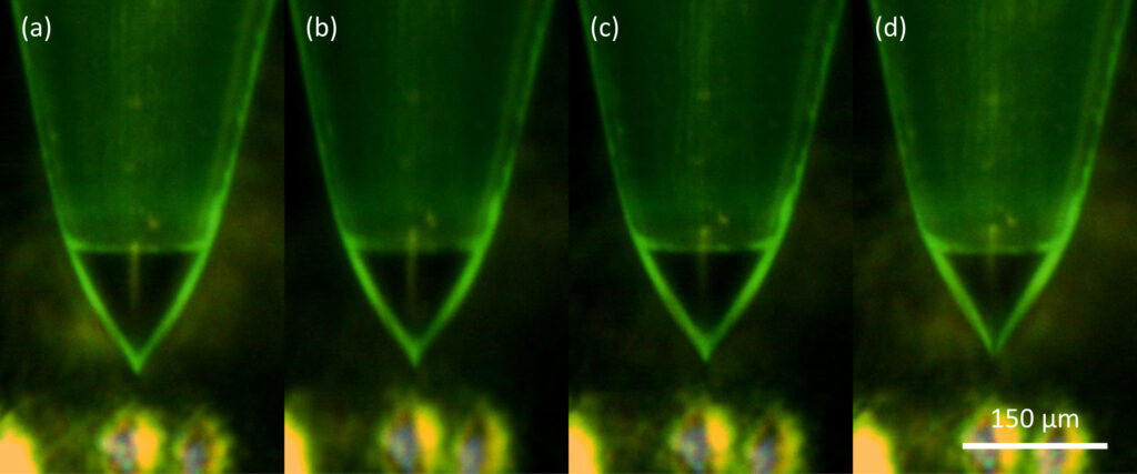
Electrospray engines produce thrust by shooting out a stream of highly charged droplets. The MIT researchers used a precise fabrication method that enhances the electrohydrodynamic reaction that generates these droplets. (Image courtesy of the researchers)
Since electrospray engines utilize propellant more efficiently than the powerful, chemical rockets used on the launchpad, they are better suited for precise, in-orbit maneuvers. The thrust generated by an electrospray emitter is tiny, so electrospray engines typically use an array of emitters that are uniformly operated in parallel.
However, these multiplexed electrospray thrusters are typically made via expensive and time-consuming semiconductor cleanroom fabrication, which limits who can manufacture them and how the devices can be applied.
To help break down barriers to space research, MIT engineers have demonstrated the first fully 3D-printed, droplet-emitting electrospray engine. Their device, which can be produced rapidly and for a fraction of the cost of traditional thrusters, uses commercially accessible 3D printing materials and techniques. The devices could even be fully made in orbit, as 3D printing is compatible with in-space manufacturing.
By developing a modular process that combines two 3D printing methods, the researchers overcame the challenges involved in fabricating a complex device comprising macroscale and microscale components that must work together seamlessly.
Their proof-of-concept thruster comprises 32 electrospray emitters that operate together, generating a stable and uniform flow of propellant. The 3D-printed device generated as much or more thrust than existing droplet-emitting electrospray engines. With this technology, astronauts might quickly print an engine for a satellite without needing to wait for one to be sent up from Earth.
“Using semiconductor manufacturing doesn’t match up with the idea of low-cost access to space. We want to democratize space hardware. In this work, we are proposing a way to make high-performance hardware with manufacturing techniques that are available to more players,” said Luis Fernando Velásquez-García, a principal research scientist in MIT’s Microsystems Technology Laboratories (MTL) and senior author of a paper describing the thrusters, which appears in Advanced Science.
He is joined on the paper by lead author Hyeonseok Kim, an MIT graduate student in mechanical engineering.
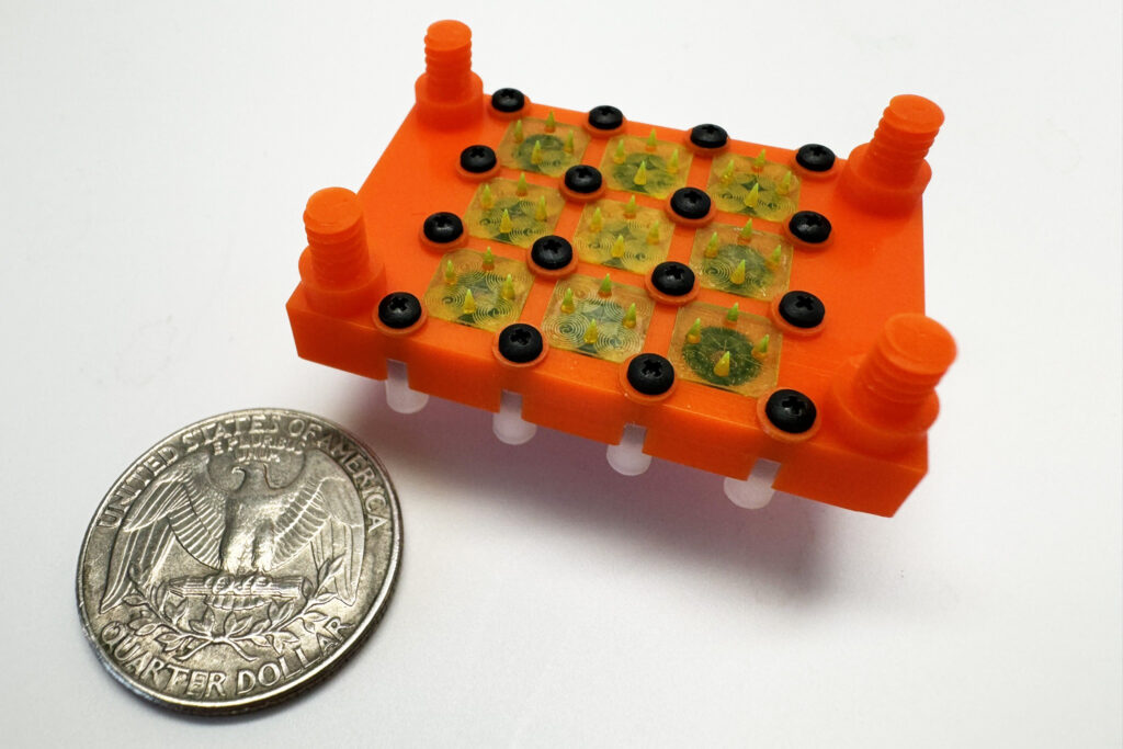
MIT engineers have demonstrated the first fully 3D-printed, droplet-emitting electrospray engine. The device, which would be ideal for enabling small satellites to make in-orbit maneuvers, can be produced for a fraction of the cost of traditional thrusters. (Image courtesy of the researchers)
A modular approach
An electrospray engine has a reservoir of propellant that flows through microfluidic channels to a series of emitters. An electrostatic field is applied at the tip of each emitter, triggering an electrohydrodynamic effect that shapes the free surface of the liquid into a cone-shaped meniscus that ejects a stream of high-speed charged droplets from its apex, producing thrust.
The emitter tips need to be as sharp as possible to attain the electrohydrodynamic ejection of propellant at a low voltage. The device also requires a complex hydraulic system to store and regulate the flow of liquid, efficiently shuttling propellant through microfluidic channels.
The emitter array is composed of eight emitter modules. Each emitter module contains an array of four individual emitters that must work in unison, forming a larger system of interconnected modules.
“Using a one-size-fits-all fabrication approach doesn’t work because these subsystems are at different scales. Our key insight was to blend additive manufacturing methods to achieve the desired outcomes, then come up with a way to interface everything so the parts work together as efficiently as possible,” Velásquez-García said.
To accomplish this, the researchers utilized two different types of vat photo polymerization printing (VPP). VPP involves shining light onto a photosensitive resin, which solidifies to form 3D structures with smooth, high-resolution features.
The researchers fabricated the emitter modules using a VPP method called two-photon printing. This technique utilizes a highly focused laser beam to solidify resin in a precisely defined area, building a 3D structure one tiny brick, or voxel, at a time. This level of detail enabled them to produce extremely sharp emitter tips and narrow, uniform capillaries to carry propellant.
The emitter modules are fitted into a rectangular casing called a manifold block, which holds each in place and supplies the emitters with propellant. The manifold block also integrates the emitter modules with the extractor electrode that triggers propellant ejection from the emitter tips when a suitable voltage is applied. Fabricating the larger manifold block using two-photon printing would be infeasible because of the method’s low throughput and limited printing volume.
Instead, the researchers used a technique called digital light processing, which utilizes a chip-sized projector to shine light into the resin, solidifying one layer of the 3D structure at a time.
“Each technology works very well at a certain scale. Combining them, so they work together to produce one device, lets us take the best of each method,” Velásquez-García said.
Propelling performance
But 3D printing the electrospray engine components is only half the battle. The researchers also conducted chemical experiments to ensure the printing materials were compatible with the conductive liquid propellant. If not, the propellant might corrode the engine or cause it to crack, which is undesirable for hardware meant for long-term operation with little to no maintenance.
They also developed a method to clamp the separate parts together in a way that avoids misalignments, which could hamper performance, and ensures the device remains watertight.
In the end, their 3D-printed prototype was able to generate thrust more efficiently than larger, more expensive chemical rockets and outperformed existing droplet electrospray engines.
The researchers also investigated how adjusting the pressure of propellant and modulating the voltage applied to the engine affected the flow of droplets. Surprisingly, they achieved a wider range of thrust by modulating the voltage. This could eliminate the need for a complex network of pipes, valves, or pressure signals to regulate the flow of liquid, leading to a lighter, cheaper electrospray thruster that is also more efficient.
“We were able to show that a simpler thruster can achieve better results,” Velásquez-García said.
The researchers want to continue exploring the benefits of voltage modulation in future work. They also want to fabricate denser and larger arrays of emitter modules. In addition, they may explore the use of multiple electrodes to decouple the process of triggering of the electrohydrodynamic ejection of propellant from setting up the shape and speed of the emitted jet. In the long run, they also hope to demonstrate a CubeSat that utilizes a fully 3D-printed electrospray engine during its operation and deorbiting.
This research is funded, in part, by a MathWorks fellowship and the NewSat Project, and was carried out, in part, using MIT.nano facilities.
This article is reprinted with permission of MIT News (http://news.mit.edu/).
Source:
https://news.mit.edu/2025/mit-engineers-develop-fully-3d-printed-electrospray-engine-0212
NASA 3D-Printed Antenna Takes Additive Manufacturing to New Heights
The antenna, the result of a collaboration involving engineers within NASA’s Scientific Balloon Program and the agency’s Space Communications and Navigation (SCaN) program, was created to showcase the capabilities of low-cost design and manufacturing.
By Kendall Murphy
NASA’s Goddard Space Flight Center, Greenbelt, Maryland
In fall 2024, NASA developed and tested a 3D-printed antenna to demonstrate a low-cost capability to communicate science data to Earth. The antenna, tested in flight using an atmospheric weather balloon, could open the door for using 3D printing as a cost-effective development solution for the ever-increasing number of science and exploration missions.
Printing
For this technology demonstration, engineers from NASA’s Near Space Network and Goddard Space Flight Center’s 3D Printing of Electronics group designed and printed an antenna, tested it with the network’ relay satellites, and then flew it on a weather balloon, in just three months.
The 3D printing process, also known as additive manufacturing, creates a physical object from a digital model by adding multiple layers of material on top of each other, usually as a liquid, powder, or filament. The bulk of the 3D-printed antenna uses a low electrical resistance, tunable, ceramic-filled polymer material.
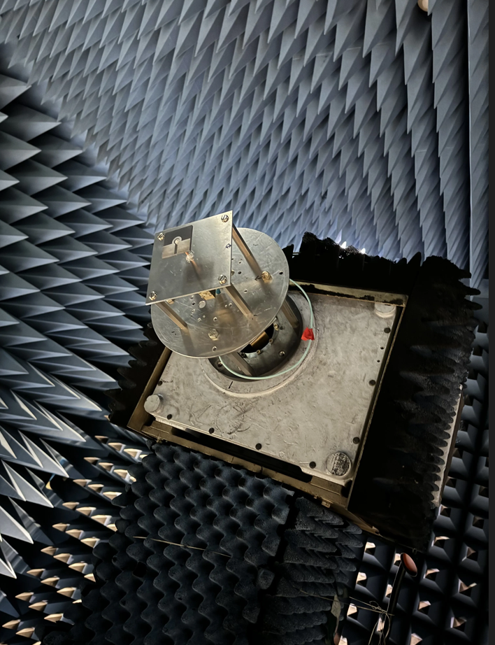
NASA Goddard’s anechoic chamber eliminates echoes and reflections of electromagnetic waves to simulate the relative “quiet” of space. Here, the antenna is installed on the mast of the anechoic chamber. (Credits: NASA/Peter Moschetti)
Using a printer supplied by Fortify, the team had full control over several of the electromagnetic and mechanical properties that standard 3D printing processes do not. Once NASA acquired the printer, this technology enabled the team to design and print an antenna for the balloon in a matter of hours. Teams printed the conductive part of the antenna with one of several different conductive ink printers used during the experiment.
For this technology demonstration, the network team designed and built a 3D-printed magneto-electric dipole antenna and flew it on a weather balloon. A dipole antenna is commonly used in radio and telecommunications. The antenna has two “poles,” creating a radiation pattern similar to a donut shape.
Testing
The antenna, a collaboration between engineers within NASA’s Scientific Balloon Program and the agency’s Space Communications and Navigation (SCaN) program, was created to showcase the capabilities of low-cost design and manufacturing.
Following manufacturing, the antenna was assembled and tested at NASA’s Goddard Space Flight Center in Greenbelt, Maryland, in the center’s electromagnetic anechoic chamber.
The anechoic chamber is the quietest room at Goddard—a shielded space designed and constructed to both resist intrusive electromagnetic waves and suppress their emission to the outside world. This chamber eliminates echoes and reflections of electromagnetic waves to simulate the relative “quiet” of space.
To prepare for testing, NASA intern Alex Moricette installed the antenna onto the mast of the anechoic chamber. The antenna development team used the chamber to test its performance in a space-like environment and ensure it functioned as intended.
Once completed, NASA antenna engineers conducted final field testing at NASA’s Columbia Scientific Balloon Facility in Palestine, Texas, before liftoff.
The team coordinated links with the Near Space Network’s relay fleet to test the 3D-printed antenna’s ability to send and receive data.
The team monitored performance by sending signals to and from the 3D-printed antenna and the balloon’s planned communications system, a standard satellite antenna. Both antennas were tested at various angles and elevations. By comparing the 3D-printed antenna with the standard antenna, they established a baseline for optimal performance.
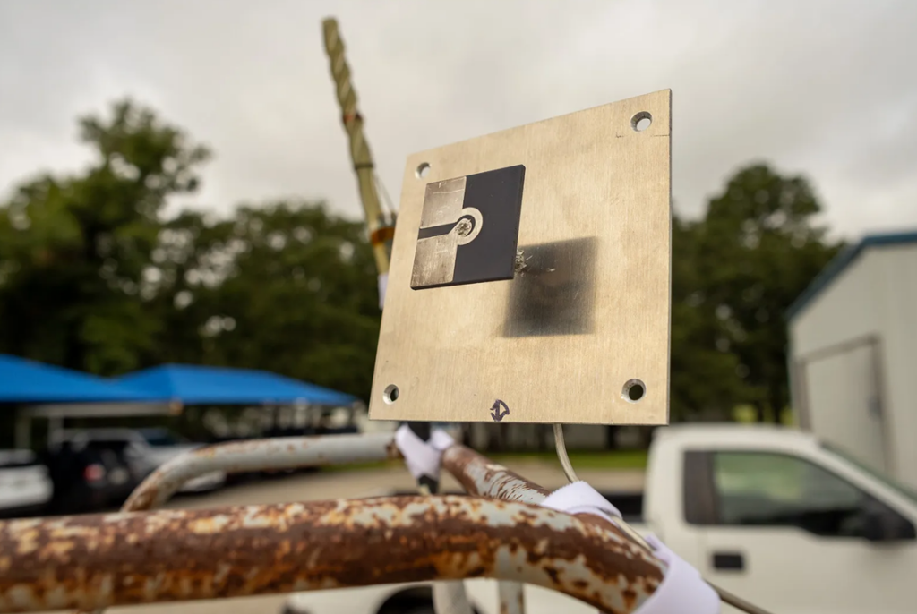
Field testing was performed at NASA’s Columbia Scientific Balloon Facility in Palestine, Texas, prior to liftoff. To do this, the 3D-printed antenna was mounted to a ladder. (Credits: NASA/Peter Moschetti)
In the Air
During flight, the weather balloon and hosted 3D-printed antenna were tested for environmental survivability at 100,000 feet and were safely recovered.
For decades, NASA’s Scientific Balloon Program, managed by NASA’s Wallops Flight Facility in Virginia, has used balloons to carry science payloads into the atmosphere. Weather balloons carry instruments that measure atmospheric pressure, temperature, humidity, wind speed, and direction. The information gathered is transmitted back to a ground station for mission use.
The demonstration revealed the team’s anticipated results: that with rapid prototyping and production capabilities of 3D printing technology, NASA can create high-performance communication antennas tailored to mission specifications faster than ever before.
Implementing these modern technological advancements is vital for NASA, not only to reduce costs for legacy platforms but also to enable future missions.
The Near Space Network is funded by NASA’s SCaN (Space Communications and Navigation) program office at NASA Headquarters in Washington. The network is operated out of NASA’s Goddard Space Flight Center in Greenbelt, Maryland.
Kendall Murphy is a technical writer for the NASA Space Communications and Navigation program office. She specializes in internal and external engagement, educating readers about space communications and navigation technology.
This article was originally published on NASA.gov.
Source:
https://www.nasa.gov/technology/nasa-3d-printed-antenna-takes-additive-manufacturing-to-new-heights/